16.60. rig_calibrator
The rig_calibrator program takes as input image and/or depth+image
datasets acquired with one or more rigs, each having one or more
cameras. It finds the relationship among the rig sensors, the pose of
each camera image, and refines the intrinsics of each sensor.
This tool was created as part of the ISAAC project.
The rig_calibrator program was extensively tested with actual
hardware and can model many real-world issues encountered with a
rig. Its output can be used to create a fused surface mesh with
seamless texture from each of its sensors, and, for ground data,
also terrain models and orthoimages.
The intrinsics of the sensors and each camera pose can also be optimized without the rig assumption. Then the sensors can acquire data at unrelated times (e.g., years apart). In that case the transforms among the sensors on the rig are not modeled, but any group of images acquired with the same sensor still share intrinsics.
The Theia package is invoked (and shipped with ASP) to find the initial camera poses (Section 16.76).
See Section 10.1 for a solved example, Section 10.2 for a larger example covering a full ISS module, and Section 10.3 for an example using MSL Curiosity rover images.
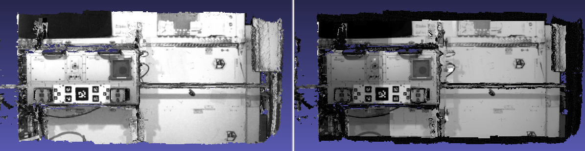
Fig. 16.27 Textures obtained with the nav_cam and sci_cam rig cameras,
(left and right) projected onto the mesh obtained with the
haz_cam depth+image camera. The textures are nearly seamless
and agree very well when overlaid, which shows that the rig
calibration was successful. Note that the sci_cam pictures (on
the right) have some lightning variation due to the fact that
auto-exposure was used. The images show a portion of the Granite
Lab at NASA Ames.
16.60.1. Capabilities
The cameras on the rig may be purely image cameras, or may have a depth component. In the latter case, the transform from a camera’s depth to image coordinate system is modeled.
No calibration target is assumed, so the image/depth data are acquired in situ.
The solved-for camera poses and relationships among sensors can be registered to real-world coordinates via user-selected control points.
All images acquired with one sensor are assumed to share intrinsics. The user may choose which intrinsics of which sensor are optimized or kept fixed, while the rig transforms and camera poses are optimized.
There can be zero, one, or more rigs.
It is not assumed that the rig sensors have a shared field of view. Yet, a surface seen in one sensor should at some point be seen also in other sensors.
The sensors on the rig may acquire data simultaneously or not. In the latter case one sensor is expected to acquire data frequently enough to be used to bracket data from the other sensors in time using bilinear interpolation of the camera poses (if the rig assumption is used).
A known time offset among the clocks of the various sensors on the rig is modeled and can be optimized. (By default no offset is assumed.)
A preexisting mesh of the surface being imaged can be used as a constraint (rays corresponding to the same feature must intersect close to the mesh). Otherwise one can constrain the triangulated points to not move too far from their original values.
Several quality metrics are printed on output, error reports are saved to disk, and for each image with its optimized camera a textured mesh with that image is created, for visual examination of any misalignments (if an input mesh is given).
16.60.2. Input data conventions
Each rig sensor must have a name, such as ref_cam, alt_cam,
etc. Each image must have a timestamp and be associated with a sensor.
This information can be specified with a file / directory structure
or in a list.
16.60.2.1. File name convention
If an image name (without directory) has a timestamp followed by a sensor string as part of its name, those will be parsed. Example:
my_images/<text>10004.6<text><sensor name><text>.jpg
The last encountered sequence of digits (optionally followed by decimal period and more digits) before the sensor name will be the timestamp. The earliest encountered string matching the sensor name will be used.
It is strongly suggested to not have any other digits in the image name, as that may confuse the parser.
An example of this naming convention is in Section 10.4.
16.60.2.2. Directory structure
The images can be organized in directories according to the convention:
<image dir>/<sensor name>/<timestamp><separator><tag>.<extension>
For example, two images acquired at time 1004.6 can be named:
my_images/ref_cam/10004.6_ref_cam.jpg
my_images/alt_cam/10004.6_alt_cam.jpg
16.60.2.3. List format
With the --image-sensor-list option, can pass in a list, in which each line
can look as:
<image dir>/image.tif ref_cam 10004.6
The second entry is the sensor name and the third is the timestamp.
16.60.2.4. Assumptions about images
All image names (without directory path) must unique.
The images are expected to be 8 or 16 bit, with .jpg, .png, or .tif extension.
16.60.2.5. Assumptions about the timestamp
A timestamp that is part of a file name must consist only of digits and a decimal period. Anything starting with another character (including another period) will not be part of the timestamp. Hence, a value like 123.4e+5 will be converted to 123.4.
If the rig constraint is used (omitting --no-rig), and the sensors acquire
the images at independent times, the timestamp must represent the precise image
acquisition time, in seconds, in double precision.
Without the rig constraint, or if all the sensors on the rig take pictures
simultaneously, the only assumption is that images have the same timestamp only
if taken at the same time, with the precise timestamp value not used
(but one must set --bracket-len to a small value). See also
--num-overlaps.
The following bash script can copy the images to new names of the form
dir/<sensor>/<timestamp><sensor>.<ext>:
mkdir -p new_images/my_cam
ext=".jpg"
((timestamp=100000))
for image in $(ls old_images/*${ext}); do
    /bin/cp -fv $image new_images/my_cam/${timestamp}.my_cam${ext}
    ((timestamp++))
done
16.60.2.6. Depth data
If for some images there is depth data, a depth data file must have the same
name as the corresponding image, but with a .pc extension. Example:
my_images/alt_cam/10004.6_alt_cam.pc
All such depth cloud files will be loaded automatically alongside images if present. See Section 16.60.14 for the file format.
16.60.3. The reference sensor
With the rig constraint, if each sensor acquires images independently, one of the sensors, named the reference sensor, should acquire images frequently enough to help bracket the other sensors in time using bilinear pose interpolation.
16.60.4. Configuration file
What is known about the rig, or set of rigs, should be specified in a plain text file, with the following syntax:
# Anything after the pound sign is a comment
ref_sensor_name: <string>

# For each sensor on the rig, specify the following:
sensor_name: <string>
focal_length: <double> # units of pixel
optical_center: <double double> # units of pixel
distortion_coeffs: <n doubles>
distortion_type: <string>
image_size: <int, int>
distorted_crop_size: <int int>
undistorted_image_size: <int int>
ref_to_sensor_transform: <12 doubles>
depth_to_image_transform: <12 doubles>
ref_to_sensor_timestamp_offset: <double>
Example (only one of the N sensors is shown):
ref_sensor_name: nav_cam

sensor_name: nav_cam
focal_length: 621.04422
optical_center: 580.56426999999996 495.51236
distortion_coeffs: 1.0092038999999999
distortion_type: fov
image_size: 1280 960
distorted_crop_size: 1280 960
undistorted_image_size: 1500 1200
ref_to_sensor_transform: 1 0 0 0 1 0 0 0 1 0 0 0
depth_to_image_transform: 1 0 0 0 1 0 0 0 1 0 0 0
ref_to_sensor_timestamp_offset: 0
If there is more than one sensor on the rig, need to create a new value for
sensor_name, and add a block as above for each sensor (without a new
ref_sensor_name).
The first specified sensor must be the reference one.
If there is more than one rig, there should be a new line having
ref_sensor_name, and then continue as above.
See a full example with two rigs in Section 10.2.13.
The lens distortion model can be one of no_distortion (zero distortion
parameters), fov (1 distortion parameter), fisheye (4 distortion
parameters), or radtan (radial-tangential, 4 or 5 distortion parameters).
The fisheye and radtan distortion models are the same as in OpenCV. The
fisheye model with one distortion parameter will be cast to fov (this is
for backward compatibility). See Section 20.1 for more details.
The ref_to_sensor_transform field has the rotation (9 doubles, stored
row after row) and translation (3 doubles) transform from the
reference sensor to the sensor with given name, while
depth_to_image_transform is the transform from the depth to image
coordinate systems of a given depth+image sensor. These must be set to
the identity transform (example below) if not known or not applicable.
That is usually the case for the first invocation of this tool, when
the ref_to_sensor_transform values are initialized based on the
camera poses of each input camera (unless
--use-initial-rig-transforms is set).
The value ref_to_sensor_timestamp_offset, measured in seconds, is
what should be added to the reference camera clock to get the time in
current sensor’s clock. Set to 0 if the clocks are synchronized.
The image_size field has the image dimensions (width and height).
The distorted_crop_size has the dimensions of the region whose
center is also the image center in which the given distortion model is
valid. Normally it should be the whole image. The
undistorted_image_size has a somewhat generous overestimate of the image
dimensions after undistortion.
Educated guess can be provided for the quantities that are not known. This tool can be used to optimize the focal length, optical center, and distortion coefficients (the latter requires many interest point matches, espcially around image corners).
The undistorted image size also need not
be known accurately. A tighter distorted_crop_size can help for
images with strong distortion if the distortion model is not
expressive enough to fit it precisely. But this then also eliminates
interest point matches in the corners of the image, which is not
good when solving for lens distortion.
A file in the same format will be written in the output directory, with the name:
<output dir>/rig_config.txt
This time the transforms among the rig sensors will be known, having been computed and optimized.
Such a file can be read with the option --rig-config.
16.60.5. Output files
The optimized rig configuration in the format described in Section 16.60.4 is saved to:
<output dir>/rig_config.txt
The image names, camera poses, and interest point matches are stored
in the NVM format. These are determined using the Theia
structure-from-motion software, and are read by rig_calibrator via the
--nvm option. The optimized camera poses and inlier interest point
matches will be written in the same format when this program finishes.
Then the output nvm file name is:
<output dir>/cameras.nvm
In this file, the interest point matches are offset relative to the
optical center. This file can be passed in to a new invocation
rig_calibrator via --nvm.
The optical centers per image are written separately, to:
<output dir>/cameras_offsets.txt
This is because these are not part of the .nvm file format.
If the option --save-nvm-no-shift is specified, the additional
file:
<output dir>/cameras_no_shift.nvm
will be saved, in the same format as above, but without interest
points being shifted relative to the optical center for the
corresponding image. This file is is easier to plot, as there is
no shift to undo, with the latter needing to be stored separately.
To read this back, use --read-nvm-no-shift.
The produced .nvm files can be visualized with stereo_gui
(Section 16.72.9.4). A submap can be extracted with sfm_submap
(Section 16.65).
In addition, a plain text file having just the list of images and world-to-camera poses will be written, with the name:
<output dir>/cameras.txt
Each line in this file has the format:
<image dir>/<sensor name>/<timestamp>.<extension> <12 doubles>
Here, the 12 values are the rows of the world-to-camera rotation and
then the world-to-camera translation. See the --camera-poses
option (Section 16.60.17) for how this file can
be read back in. Note that camera’s position and orientation in world
coordinates are determined by taking the inverse of this rotation +
translation transform.
The inlier residuals for each camera (that is, norm of reprojection errors, with reprojection errors defined as the difference of interest points and projection of triangulated interest points back in the camera), before and after optimization, are saved to:
<output dir>/<sensor name>-initial-residuals.txt
<output dir>/<sensor name>-final-residuals.txt
in the format:
distorted_pixel_x distorted_pixel_y norm(residual_x, residual_y)
The convergence angle percentiles for each pair of images having inlier matches, together with the number of such matches for each pair, are saved to:
<output dir>/convergence_angles.txt
The option --export-to-voxblox saves files that can be used with voxblox_mesh (Section 16.79).
The list of images is saved (one per line) to:
<output dir>/image_list.txt
How to export the data for use in bundle adjustment is discussed in Section 16.60.15.
16.60.6. Examples
A step-by-step-example (Section 10.1).
A larger example covering a full ISS module (Section 10.2).
An example using MSL Curiosity rover images (Section 10.3).
An orbital rig with DEM constraints (Section 10.4).
16.60.7. Notes
Optimizing the camera poses (without control points or a preexisting mesh constraint) can change the scale and orientation of the camera set.
The output directory will have the optimized rig configuration and camera poses for all images. These can be used as inputs for a subsequent invocation, if needed to fine-tune things.
16.60.8. Constraints on rig transforms
In this section we assume that --no-rig is not set, so we have a rig.
If --camera-poses-to-float lists all sensors, all cameras can change in
any way, as long as they are tied together by an (evolving) rig at all times.
If only the reference sensor is mentioned in --camera-poses-to-float, the
cameras for this sensor will change freely, but the other cameras will only
change as necessary to respect the rig constraint, while the rig configuration
stays fixed.
If the reference sensor is not specified in --camera-poses-to-float, the
cameras for this sensor will stay fixed, while the transform from the reference
sensor to another sensor will change only if that sensor is mentioned in
--camera-poses-to-float.
An analogous parameter is --depth-to-image-transforms-to-float.
Independent of these, the options --fix-rig-translations and
--fix-rig-rotations, used separately or together, can constrain either the
translation or rotation component of all transforms from the reference sensor to
the other sensors.
These options are described in Section 16.60.17.
16.60.9. Constraints on cameras
The parameter --camera-position-uncertainty constrains how far cameras can move.
This specifies the expected uncertainty (1 sigma, in meters) for camera positions.
Smaller values create tighter constraints that may impede convergence. This is added
to the cost function as the sum of squares of differences between initial and current
camera positions, divided by the uncertainty.
16.60.10. Constraints on triangulated points
Triangulated points are, by default, set to not move too far, after
registration. See --tri-weight and --tri-robust-threshold.
The --heights-from-dem option can constrain triangulated points to be close
to a DEM. This is applicable for orbital images. The logic is as for bundle
adjustment (Section 12.2.1.3). An example is in Section 10.4.
Additional constraints are --depth-mesh-weight and --depth-tri-weight
(Section 16.60.17).
16.60.11. Determination of scale and registration
The cameras produced so far are in an arbitrary coordinate system. This section describes how to register them to known Cartesian coordinates. For registering rover cameras to a DEM, see Section 10.3.10.
To transform the system of cameras to world coordinates, it is necessary to know the Cartesian coordinates of at least three control points in the scene, and then to pick the pixel of coordinates of each of these points in at least two images.
All images used in registration must be for the same sensor. To find the pixel coordinates, open, for example, a subset of the camera images for one of the sensors in Hugin, such as:
hugin <image dir>/<sensor name>/*.jpg
It will ask to enter a value for the FoV (field of view). That value is not important since we won’t use it. One can input 10 degrees, for example.
Go to the “Expert” interface, choose a couple of distinct images, and click on a desired control point in both images. Make sure the left and right image are not the same or highly similar, as that may result in poor triangulation and registration. Add that point. Then repeat this process for all control points.
Save the Hugin project to disk. Create a separate text file which contains the world coordinates of the control points picked earlier, with each line in the “x y z” format, and in the same order as the Hugin project file. That is to say, if a control point was picked in several image pairs in Hugin, it must show up also the same number of times in the text file, in the same order. In the xyz text file all lines starting with the pound sign (#) are ignored, as well as all entries on any line beyond three numerical values.
The dataset from Section 10.1 has examples of files used for registration, and shows how to pass these to the tool.
After registration is done, it will print each transformed coordinate point from the map and its corresponding measured point, as well as the error among the two. That will look as follows:
transformed computed xyz -- measured xyz -- error norm (meters)
-0.0149 -0.0539  0.0120 --  0.0000  0.0000  0.0000 --  0.0472 img1.jpg img2.jpg
 1.8587  0.9533  0.1531 --  1.8710  0.9330  0.1620 --  0.0254 img3.jpg img4.jpg
Each error norm (last value), is the distance between a measured 3D point and its computed value based on the registered cameras. If some of them are too large, may be the measurements have some error, or the camera poses or intrinsics are not accurate enough.
Note that the registration happens before the optimization, and that
can move the cameras around somewhat. Hence the registration
is redone after the last optimization pass, unless
the flag --skip-post-registration is specified.
The initial registration does not change the depth-to-image transforms, as those are presumed to be reasonably known, unlike the image camera poses, which are determined normally using Theia and are in an arbitrary coordinate system. After the cameras and all transforms are optimized, including the depth-to-image transforms, if present, and if registration happens at the end, these transforms will be changed as well, for consistency with the transforms among the image cameras.
If the images cover a large area, it is suggested to use registration points distributed over that area. Registration may not always produce perfect results since a structure-from-motion solution may drift over large distances.
The software does not force the camera poses to move individually to fit better the control points. Therefore, the cameras are always kept self-consistent, then the camera configuration has a single registration transform applied to it to fit the control points. The only approach to make the cameras individually conform more faithfully to what is considered accurate geometry is to use the mesh constraint, if such a prior surface mesh is available.
16.60.12. Quality metrics
The rig calibrator will print out some statistics showing the residual errors before and after each optimization pass (before outlier removal at the end of the pass), as follows:
The 25, 50, 75, and 100th percentile residual stats after opt
depth_mesh_x_m: 0.0018037 0.0040546 0.011257 0.17554 (742 residuals)
depth_mesh_y_m: 0.0044289 0.010466 0.025742 0.29996 (742 residuals)
depth_mesh_z_m: 0.0016272 0.0040004 0.0080849 0.067716 (742 residuals)
depth_tri_x_m: 0.0012726 0.0054119 0.013084 1.6865 (742 residuals)
depth_tri_y_m: 0.0010357 0.0043689 0.022755 3.8577 (742 residuals)
depth_tri_z_m: 0.00063148 0.0023309 0.0072923 0.80546 (742 residuals)
haz_cam_pix_x: 0.44218 0.99311 2.1193 38.905 (819 residuals)
haz_cam_pix_y: 0.2147 0.49129 1.3759 95.075 (819 residuals)
mesh_tri_x_m: 0.0002686 0.00072069 0.014236 6.3835 (5656 residuals)
mesh_tri_y_m: 9.631e-05 0.00032232 0.057742 9.7644 (5656 residuals)
mesh_tri_z_m: 0.00011342 0.00031634 0.010118 1.0238 (5656 residuals)
nav_cam_pix_x: 0.098472 0.28129 0.6482 155.99 (47561 residuals)
nav_cam_pix_y: 0.11931 0.27414 0.55118 412.36 (47561 residuals)
sci_cam_pix_x: 0.33381 0.70169 1.4287 25.294 (2412 residuals)
sci_cam_pix_y: 0.24164 0.52997 0.90982 18.333 (2412 residuals)
These can be helpful in figuring out if the calibration result is
good. The errors whose name ends in “_m” are in meters and measure
the absolute differences between the depth clouds and mesh
(depth_mesh), between depth clouds and triangulated points
(depth_tri), and between mesh points and triangulated points
(mesh_tri), in x, y, and z, respectively. The mesh residuals will
be printed only if a mesh is passed on input and if the mesh-related
weights are positive.
Some outliers are unavoidable, hence some of these numbers can be big
even if the calibration overall does well (the robust threshold set
via --robust-threshold does not allow outliers to dominate). See
the option --max-reprojection-error for filtering outliers. It is
best to not filter them too aggressively unless one has very high
confidence in the modeling of the cameras.
Source of errors can be, as before, inaccurate intrinsics, camera poses, or insufficiently good modeling of lens distortion.
When each rig sensor has its own clock, or acquires images at is own
rate, the discrepancy among the clocks (if the timestamp offsets are
not set correctly) or insufficiently tight bracketing (cameras moving
too much between acquisitions meant to serve as brackets) may be source
of errors as well. In this case one can also try the tool with
the --no-rig option, when the cameras are decoupled and see if this
makes a difference.
16.60.13. Handling failures
This software was very carefully tested in many circumstances, and it is though to be, by and large, correct, and it should normally co-register all images to within 0-5 pixels, and likely even better if distortion is modeled accurately. (Quality can be verified as above, by projecting the camera images onto a mesh obtained either from depth clouds or stereo.)
If it performs poorly, it may be because:
Image timestamps are not accurate. Then try using the
--no-rigoption, adjust the timestamp offsets, or use tighter bracketing with--bracket-len.Distortion is very strong and not modeled well. Then reduce the domain of each image by making
distorted_crop_sizesmaller in the rig configuration, or switch to a different distortion model, or allow distortion to be optimized by this tool.The best-fit distortion model can be inaccurate unless there are many interest point matches, especially in the image periphery. See Section 16.76.3 for how to get more matches. The produced matches should be visualized in
stereo_gui(Section 16.72.9.4).Some image pairs have insufficient matches, which may result in poor initial camera poses. This can be addressed as for distortion, in the paragraph above. This tool has good robustness to that when the rig constraint is used (so without
--no-rig) as then the transforms between rig sensors are found by using the median of transforms derived from individual image pairs, and the same rig transform applies for all acquisitions.Some weights passed in (e.g.,
--tri-weight,--mesh-tri-weight) may be too high and prevent convergence.The options
--camera-poses-to-float(Section 16.60.8),--intrinsics-to-float,--depth-to-image-transforms-to-float, were not all specified and hence some optimizations did not take place.
For understanding issues, it is strongly suggested to drastically
reduce the problem to perhaps one or two images from each sensor, and
turn on the debugging flags --save-matches,
--export-to-voxblox, --save-transformed-depth-clouds,
--out-texture-dir. Then, the images can be projected individually
onto a mesh, and/or individual transformed clouds can be inspected.
See an example output in Fig. 16.27.
See note on validation in Section 10.3.10.4 for when working with orbital or ground-level images.
One should also look at the statistics printed by the tool.
16.60.14. Point cloud file format
The depth point clouds (for the depth component of cameras, if
applicable) are saved to disk in binary. The first three entries are
of type int32, having the number of rows, columns and channels (whose
value is 3). Then, one iterates over rows, for each row iterates over
columns, and three float32 values corresponding to x, y, z
coordinates are read or written. If all three values are zero, this
point is considered to be invalid, but has to be read or written
to ensure there exists one depth point for each corresponding image pixel.
Note that the float32 datatype has limited precision, but is adequate,
unless the measurements are ground data taken from a planet’s orbit.
16.60.15. Interfacing with bundle_adjust
This program’s program’s output control network in .nvm format (including camera
poses and interest point matches between the images) can be read by
bundle_adjust (Section 16.5), and vice-versa. The details are in
Section 16.5.10.3.
The optimized cameras produced with rig_calibrator can be saved in the ASP
Pinhole format (Section 20.1) with the option
--save-pinhole-cameras.
The list of saved cameras will be in the file:
rig_out/camera_list.txt
while the list of input images will be in:
rig_out/image_list.txt
Here and below we assume that the output directory is rig_out.
If rig_calibrator is called with the option --save-matches, it will save
the inlier interest point matches in the ASP bundle_adjust
(Section 16.5) format with the proper naming convention
(Section 16.5.10.1).
These can then be inspected in stereo_gui
(Section 16.72.9.2) as:
stereo_gui $(cat rig_out/image_list.txt) \
  rig_out/matches/run --pairwise-matches
If both the matches and cameras are saved, bundle_adjust can be
invoked as:
bundle_adjust                              \
  --image-list rig_out/image_list.txt      \
  --camera-list rig_out/camera_list.txt    \
  --inline-adjustments                     \
  --match-files-prefix rig_out/matches/run \
  -o ba/run
For a large number of images it is preferable to use the NVM file instead of the
match files as input to bundle_adjust, as described earlier.
In order for exporting data this way to work, all input image names (without directory path) must be unique, as the ASP bundle adjustment counts on that. See the input naming convention in Section 16.60.2.
How to register the produced cameras to the ground is discussed in Section 10.3.10.
16.60.16. Usage
rig_calibrator --rig-config <rig_config.txt>  \
  --nvm <input.nvm>                           \
  --image-sensor-list <image_sensor_list.txt> \
  -o <output_dir> [options]
16.60.17. Command-line options
- --rig-config <string (default: “”)>
Read the rig configuration from file.
- --nvm <string (default: “”)>
Read images and camera poses from this nvm file, as exported by Theia.
- --image-sensor-list <string (default: “”)>
Read image name, sensor name, and timestamp, from each line in this list. The order need not be as in the nvm file. Alternatively, a directory structure can be used. See Section 16.60.2.
- --robust-threshold <double (default: 0.5)>
Residual pixel errors and 3D point residuals (the latter multiplied by corresponding weight) much larger than this will be logarithmically attenuated to affect less the cost function. See also
--tri-robust-threshold.- --affine-depth-to-image
Assume that the depth-to-image transform for each depth + image camera is an arbitrary affine transform rather than scale * rotation + translation. See also
--float-scale.- --bracket-len <double (default: 0.6)>
Lookup non-reference cam images only between consecutive ref cam images whose distance in time is no more than this (in seconds), after adjusting for the timestamp offset between these cameras. It is assumed the rig moves slowly and uniformly during this time. A large value here will make the calibrator compute a poor solution but a small value may prevent enough images being bracketed. The timestamp (in seconds) is part of the image name. See also
--bracket-single-image.- --num-passes <integer (default: 2)>
How many passes of optimization to do. Outliers will be removed after every pass. Each pass will start with the previously optimized solution as an initial guess. Mesh intersections (if applicable) and ray triangulation will be recomputed before each pass.
- --camera-poses-to-float <string (default: “”)>
Specify the cameras for which sensors can have their poses floated. Example: ‘cam1 cam3’. See more details in Section 16.60.8.
- --fix-rig-translations
Fix the translation component of the transforms between the sensors on a rig. Works only when
--no-rigis not set.- --fix-rig-rotations
Fix the rotation component of the transforms between the sensors on a rig. Works only when
--no-rigis not set.- --camera-position-uncertainty <string (default: “”)>
Camera position uncertainty (1 sigma, in meters). This strongly constrains the movement of cameras, potentially at the expense of accuracy. Specify as a single value.
- --heights-from-dem <string (default: “”)>
Use this DEM to constrain the triangulated points. The uncertainty of the DEM is specified via
--heights-from-dem-uncertainty.- --heights-from-dem-uncertainty <double (default: -1)>
Uncertainty (1 sigma) for
--heights-from-dem. A smaller value constrains more the triangulated points to the DEM specified via--heights-from-dem.- --heights-from-dem-robust-threshold <double (default: 0.1)>
Robust threshold for residual errors in triangulated points relative to DEM specified via
--heights-from-dem. This is applied after the point differences are divided by--heights-from-dem-uncertainty. It will attenuate large height differences. Set to 0 to turn off.- --tri-weight <double (default: 0.1)>
The weight to give to the constraint that optimized triangulated points stay close to original triangulated points. A positive value will help ensure the cameras do not move too far, but a large value may prevent convergence. This does not gets set for triangulated points at which
--heights-from-demor--meshconstraints are applied.- --tri-robust-threshold <double (default: 0.1)>
The robust threshold to use with the triangulation weight. Must be positive. See also
--robust-threshold.- --use-initial-triangulated-points
Use the triangulated points from the input nvm file. Together with
--tri-weight, this ensures the cameras do not move too far from the initial solution. This will fail if additional interest point matches are created with--num-overlaps. If registration is used, the initial triangulated points are transformed appropriately.- --depth-mesh-weight <double (default: 0)>
A larger value will give more weight to the constraint that the depth clouds stay close to the mesh. Not suggested by default.
- --depth-to-image-transforms-to-float <string (default: “”)>
Specify for which sensors to float the depth-to-image transform (if depth data exists). Example: ‘cam1 cam3’.
- --depth-tri-weight <double (default: 1000)>
The weight to give to the constraint that depth measurements agree with triangulated points. Use a bigger number as depth errors are usually on the order of 0.01 meters while reprojection errors are on the order of 1 pixel.
- --float-scale
If to optimize the scale of the clouds, part of depth-to-image transform. If kept fixed, the configuration of cameras should adjust to respect the given scale. This parameter should not be used with
--affine-depth-to-imagewhen the transform is affine, rather than rigid and a scale.- --float-timestamp-offsets
If to optimize the timestamp offsets among the cameras. This is experimental.
- --camera-poses <string (default: “”)>
Read the images and world-to-camera poses from this list. The same format is used as when this tool saves the updated poses in the output directory. It is preferred to read the camera poses with the
--nvmoption, as then interest point matches will be read as well.- --initial-max-reprojection-error <double (default: 300)>
If filtering outliers, remove interest points for which the reprojection error, in pixels, is larger than this. This filtering happens when matches are created, before cameras are optimized, and a big value should be used if the initial cameras are not trusted.
- --intrinsics-to-float <string (default: “”)>
Specify which intrinsics to float for each sensor. Example: ‘cam1:focal_length,optical_center,distortion cam2:focal_length’.
- --max-ray-dist <double (default: 100)>
The maximum search distance from a starting point along a ray when intersecting the ray with a mesh, in meters (if applicable).
- --max-reprojection-error <double (default: 25)>
If filtering outliers, remove interest points for which the reprojection error, in pixels, is larger than this. This filtering happens after each optimization pass finishes, unless disabled. It is better to not filter too aggressively unless confident of the solution.
- --mesh <string (default: “”)>
Use this mesh to help constrain the calibration (in .ply format). Must use a positive
--mesh-tri-weight.- --mesh-tri-weight <double (default: 0)>
A larger value will give more weight to the constraint that triangulated points stay close to a preexisting mesh. Not suggested by default.
- --min-ray-dist <double (default: 0)>
The minimum search distance from a starting point along a ray when intersecting the ray with a mesh, in meters (if applicable).
- --no-rig
Do not assumes the cameras are on a rig. Hence, the pose of any camera of any sensor type may vary on its own and not being tied to other sensor types. See also
--camera-poses-to-float.- --num-iterations <integer (default: 100)>
How many solver iterations to perform in calibration.
- --num-threads <integer>
How many threads to use. (default: Number of cores on a machine).
- --num-match-threads <integer (default: 8)>
How many threads to use in feature detection/matching. A large number can use a lot of memory.
- -o, --out-dir <string (default: “”)>
Save in this directory the camera intrinsics and extrinsics. See also
--save-matches,--verbose.- --out-texture-dir <string (default: “”)>
If non-empty and if an input mesh was provided, project the camera images using the optimized poses onto the mesh and write the obtained .obj files in the given directory.
- --num-overlaps <integer (default: 0)>
Match an image with this many images (of all camera types for the same rig) following it in increasing order of timestamp value. Set to a positive value only if desired to find more interest point matches than read from the input nvm file. Not suggested by default.
- --no-nvm-matches
Do not read interest point matches from the nvm file. So read only camera poses. This implies
--num-overlapsis positive, to be able to find new matches.- --parameter-tolerance <double (default: 1e-12)>
Stop when the optimization variables change by less than this.
- --min-triangulation-angle <double (default: 0.01)>
If filtering outliers, remove triangulated points for which all rays converging to it make an angle (in degrees) less than this. Note that some cameras in the rig may be very close to each other relative to the triangulated points, so care is needed here.
- --registration
If true, and registration control points for the sparse map exist and are specified by
--hugin-fileand--xyz-file, register all camera poses and the rig transforms before starting the optimization. For now, the depth-to-image transforms do not change as result of this, which may be a problem. To apply the registration only, use zero iterations.- --skip-post-registration
If true and registration to world coordinates takes place, do not apply the registration again after the cameras are optimized. This is usually not recommended, unless one is quite confident that other constraints (such as using
--tri-weightor--mesh-tri-weight) are sufficient to keep the cameras from drifting.- --hugin-file <string (default: “”)>
The path to the hugin .pto file used for registration.
- --xyz-file <string (default: “”)>
The path to the xyz file used for registration.
- --read-nvm-no-shift
Read an nvm file assuming that interest point matches were not shifted to the origin.
- --save-nvm-no-shift
Save the optimized camera poses and inlier interest point matches to <out dir>/cameras_no_shift.nvm. Interest point matches are not offset relative to the optical center, which is not standard, but which allows this file to be self-contained and for the matches to be drawn with
stereo_gui.- --save-matches
Save the interest point matches (all matches and inlier matches after filtering).
stereo_guican be used to visualize these (Section 16.60.15).- --export-to-voxblox
Save the depth clouds and optimized transforms needed to create a mesh with
voxblox(if depth clouds exist).- --save-transformed-depth-clouds
Save the depth clouds with the camera transform applied to them to make them be in world coordinates.
- --save-pinhole-cameras
Save the optimized cameras in ASP’s Pinhole format (Section 16.60.15). The distortion model gets saved if it is of
radtantype (OpenCV radial-tangential distortion model).- --timestamp-offsets-max-change <double (default: 1)>
If floating the timestamp offsets, do not let them change by more than this (measured in seconds). Existing image bracketing acts as an additional constraint.
- --use-initial-rig-transforms
Use the transforms between the sensors (
ref_to_sensor_transform) of the rig specified via--rig-configto initialize all non-reference camera poses based on the reference camera poses and the rig transforms. If this option is not set, derive the rig transforms from the poses of individual cameras.- --fixed-image-list <string>
A file having a list of images (separated by spaces or newlines) whose camera poses should be fixed during optimization. These can be only reference sensor images when the rig constraint is on.
- --bracket-single-image
If more than one image from a given sensor is acquired between two consecutive reference sensor images, as measured by timestamps, keep only one, choosing the image that is closest to the midpoint of the interval formed by reference sensor timestamps. Only applicable without
--no-rig.- --extra-list <string (default: “”)>
Add to the SfM solution the camera poses for the additional images/depth clouds in this list. Use bilinear interpolation of poses in time and nearest neighbor extrapolation (within
--bracket-len) and/or the rig constraint to find the new poses (will be followed by bundle adjustment refinement). This can give incorrect results if the new images are not very similar or not close in time to the existing ones. This list can contain entries for the data already present.- --nearest-neighbor-interp
Use nearest neighbor interpolation (in time) when inserting extra camera poses.
- --verbose
Print a lot of verbose information about how matching goes.
- -v, --version
Display the version of software.
- -h, --help
Display the help message.