8.8. Lunar Reconnaissance Orbiter (LRO) NAC
This section will describe in detail how to process an LRO NAC dataset. (See also Section 4.1 for a ready-made example using a different dataset for which all inputs have already been prepared.)
8.8.1. The site
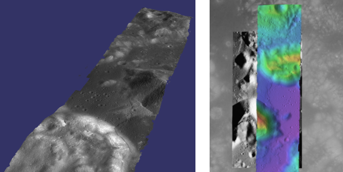
In this example we will consider a stereo pair that covers the Taurus-Littrow valley on the Moon where, on December 11, 1972, the astronauts of Apollo 17 landed. However, this stereo pair does not contain the landing site. It is slightly west; focusing on the Lee-Lincoln scarp that is on North Massif. The scarp is an 80 m high feature that is the only visible sign of a deep fault.

Fig. 8.5 Example output possible with a LROC NA stereo pair, using both CCDs from each observation, courtesy of the lronac2mosaic.py tool.
8.8.2. LRO NAC camera design
LRO has two Narrow Angle Cameras (NAC), with both acquiring image data
at the same time, so each observation consists
of two images, left and right, denoted with L and R.
These are not meant to be used as a stereo pair, as the camera
center is virtually in the same place for both, and they have very little
overlap. For stereo one needs two such observations, with a
reasonable perspective difference (baseline) among the two.
Then stereo can happen by pairing an L or R image from the first observation with an L or R image from the second. Alternatively, each observation’s L and R images can be stitched first, then stereo happens between the two stitched images. Both of these approaches will be discussed below.
8.8.3. Download
Download the experimental data records (EDR) for observations M104318871 and M104311715 from http://wms.lroc.asu.edu/lroc/search. Alternatively, search by original IDs of 2DB8 and 4C86 in the PDS.
The download will result in four files, named M104318871LE.img, M104318871RE.img, M104311715LE.img, and M104311715RE.img.
8.8.4. Preparing the inputs without stitching
The individual L and R images in an LRO NAC observation can be
used without stitching if desired to keep the original camera models.
Unstitched cameras can also be converted to CSM (Section 8.12), which
will provide a great speed up for stereo, bundle adjustment, and
Shape-from-Shading (Section 13).
We convert each .img file to an ISIS .cub camera image, initialize the SPICE kernels, and perform radiometric calibration and echo correction. Here are the steps, illustrated on one image:
f=M104318871LE
lronac2isis from = ${f}.IMG     to = ${f}.cub
spiceinit   from = ${f}.cub shape = ellipsoid
lronaccal   from = ${f}.cub     to = ${f}.cal.cub
lronacecho  from = ${f}.cal.cub to = ${f}.cal.echo.cub
Note that for these commands to succeed, ISIS and its supporting data must be downloaded, per Section 2.1.3.
8.8.5. Stitching the LE and RE observations
In this case all ISIS preprocessing of the EDRs is performed via the
lronac2mosaic.py command (Section 16.38):
lronac2mosaic.py M104318871LE.img M104318871RE.img
lronac2mosaic.py M104311715LE.img M104311715RE.img
This runs lronac2isis, lronaccal, lronacecho,
spiceinit, noproj, and handmos to create a stitched
unprojected image for each observation. In this example we don’t
mapproject the images as ASP can usually get good results. More
aggressive terrain might require an additional cam2map4stereo.py
step.
8.8.6. Running stereo
Stereo can then be run either with unstitched or stitched .cub files. Here’s an example:
parallel_stereo M104318871LE*.mosaic.norm.cub  \
  M104311715LE*.mosaic.norm.cub result/output  \
  --alignment-method affineepipolar
Check the stereo convergence angle as printed during preprocessing (Section 8.1). That angle is often too small for LRO NAC, and then the results are not going to be great.
See Section 6 for a discussion about various stereo speed-vs-quality choices. Consider using mapprojection (Section 6.1.7).
Mapprojection can also be done with the ISIS tools
(Section 11.4.2). Better mapprojection results can be
achieved by projecting on a higher resolution elevation source like
the WAC DTM. This is achieved using the ISIS command demprep and
attaching to cube files via the spiceinit SHAPE and MODEL options.