8.23. RPC camera models
Some vendors, such as GeoEye with its Ikonos and two GeoEye satellites, Airbus, with its SPOT and Pleiades satellites, the Indian Cartosat-1 satellite, PeruSat-1, the Spanish Deimos 1 and 2, etc., provide Rational Polynomial Coefficient (RPC) camera models.
(Certain providers also offer exact linescan models. ASP supports the ones from DigitalGlobe/Maxar (Section 5), PeruSat-1 (Section 8.24), Pleiades 1A/1B (Section 8.25), SPOT 5 (Section 8.26), and SPOT 6/7 (Section 8.27).)
8.23.1. About RPC
RPC represents four 20-element polynomials that map geodetic coordinates (longitude-latitude-height above datum) to image pixels. Since they are easy to implement and fast to evaluate, RPC represents a universal camera model providing a simple approximation to complex exact camera models that are unique to each vendor. The only downside is that it has less precision in our opinion compared to the exact camera models.
Our RPC read driver is GDAL. If the command gdalinfo
(Section 16.25) can identify the RPC information inside the
headers of your image files (whether that information is actually
embedded in the images, or stored separately in some auxiliary files
with a convention GDAL understands), ASP will likely be able to see it
as well. This means that sometimes we can get away with only providing
a left and right image, with no extra files containing camera
information. This is specifically the case for GeoEye, and
Cartosat-1.
Otherwise, the camera files must be specified separately in XML files, as done for DigitalGlobe/Maxar images (Section 5.2) and PeruSat-1.
See Section 8.25.6 if the input Pleiades images arrive in multiple tiles.
8.23.2. Examples
Here we work with a GeoEye dataset for Hobart, Australia. As previously stated in Section 5, these types of images are not ideal for ASP. This is both a forest and a urban area which makes correlation difficult. ASP was designed more for modeling bare rock and ice. Any results we produce in other environments is a bonus but is not our objective.
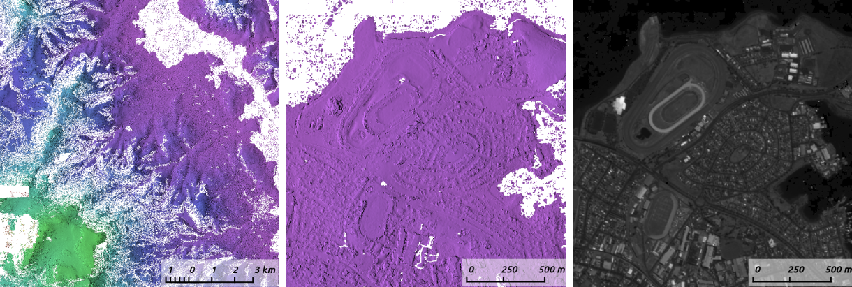
Fig. 8.52 Example colorized height map and ortho image output, produced
with point2dem (Section 16.56) and mapproject
(Section 16.41), respectively.
GoeEye’s datasets have the RPC coefficients stored as part of the images. The stereo command is then:
parallel_stereo -t rpc       \
  --stereo-algorithm asp_mgm \
  --subpixel-mode 9          \
  left.tif right.tif         \
  results/run
See Section 6 for a discussion about various speed-vs-quality choices.
For terrains having steep slopes, we recommend that images be mapprojected onto an existing DEM before running stereo. This is described in Section 6.1.7.
Next, point2dem (Section 16.56) is run:
point2dem --auto-proj-center results/run-PC.tif
For some cameras the RPC coefficients are stored in separate files ending in .RPB or _RPC.TXT (or in lower-case). These will be loaded automatically and should not be specified in the stereo command.
For Cartosat data sometimes one should overwrite the _RPC.TXT files that are present with the ones that end in RPC_ORG.TXT in order for stereo to work.
If the RPC cameras are stored separately in XML files, the stereo command is:
parallel_stereo -t rpc       \
  --stereo-algorithm asp_mgm \
  --subpixel-mode 9          \
  left.tif right.tif         \
  left.xml right.xml         \
  results/run
The RPC cameras can be bundle-adjusted (Section 16.5).
If the RPC coefficients are stored in the input images, mapproject
copies them to the output mapprojected images. If these coefficients
are in the associated .RPB or _RPC.TXT files, mapproject creates
such files for each mapprojected image.
See Section 6.1.7.7 for how parallel_stereo is invoked
with mapprojected images when the cameras are stored either separately
or part of the images.
8.23.3. Adjusted RPC cameras
It is suggested to run bundle adjustment (Section 16.5) before stereo, to ensure the cameras are self-consistent. An example is in Section 16.5.1.3.
Bundle adjustment produces .adjust files that have rotation and translation
adjustments to the original cameras. These can be passed to other ASP tools via
the --bundle-adjust-prefix option.
To make new RPC cameras, with the adjustments already applied to them, use the
bundle_adjust option --save-adjusted-rpc. These are saved in the
bundle_adjust output directory, with names ending in .adjusted_rpc.xml.
These cameras can be used with ASP and third-party software.
Any produced adjusted RPC model file can be loaded by GDAL when reading an image
(including with gdalinfo, Section 16.25) if it is renamed to have the same
name as the image but with the .xml extension, and no analogously named
.RPB or _RPC.txt files are present that may take precedence. See the
GeoTiff documentation.
Applying the adjustments refits the RPC models, and should create cameras that agree well with the ones with the adjustments applied externally.
It is strongly suggested to use the cam_test program to see how well an
input RPC camera agrees with itself, and the same for testing with the RPC
camera produced as documented here against itself (Section 16.9). With
this program, choose the value of the option --height-above-datum to be not
too far from the height offset in the RPC model, or surely within the
acceptable height range of the RPC model, as given by the height offset and
height scale.
This refitting will not work well for Umbra SAR cameras (Section 8.33), where the height scale parameter is very large and the RPC fit does not work in the full-height box, but only in a small range around the height offset.
If bundle_adjust is invoked with 0 iterations, the input RPC and refit
RPC should also be tested for agreement, as then they in principle should be
about the same.
To export an existing RPC camera to XML format without refitting it, use
cam_gen (Section 16.8.1.10).
8.23.4. Creation of RPC cameras
In addition to supporting the provided RPC models, ASP provides a
tool named cam2rpc (Section 16.7), that can be
used to create RPC camera models from ISIS and all other cameras that
ASP understands, including for non-Earth planets (currently only the
Earth, Moon and Mars are supported).
In such situations, the planet datum must be passed to the tools reading the RPC
models, via the --datum option.
8.23.5. Triangulation with RPC cameras
An RPC camera model is a black-box model, rather than one using rigorous camera geometry. It is only able to compute a pixel value in the camera given a point on the ground.
For triangulation, it is necessary to be able to calculate a ray emanating from a given pixel going to the ground. With RPC cameras, a somewhat indirect method is used.
A ray is found by determining with a solver two points on the ground that project into the same pixel, with both points within the lon-lat-height box of the RPC model.
In the latest ASP build (Section 2.1), these points are picked at +/-
min(50.0, height_scale) meters from the height offset specified in the RPC
model. A larger range does not make a difference, except for situations when
height_scale does not represent correctly the actual height range the RPC
model was fit on, such as for Umbra SAR (Section 8.33). In earlier ASP
versions, the points were picked at +/- 0.9 times the height scale, which worked
well enough except for SAR.
Another ray is found the same way for the second image. Then, the two rays are intersected as usual.
Note that the RPC model does not have the concept of camera center. This is set to a point in the lon-lat-height box that projects into the pixel (0, 0) in the camera (at maximum height in the box). This is not a serious problem as long as the camera centers are not used for modeling the orbit or controlling the camera location. Bundle adjustment and terrain reconstruction are not affected.