10.4. Orbital rig
This example shows how to produce synthetic images and cameras that model an orbital rig with two frame camera sensors, and how to use the rig_calibrator tool to refine the rig parameters, camera intrinsics, and camera poses. This example demonstrates the new DEM height constraint feature that constrains triangulated points to a reference DEM for improved accuracy.
10.4.1. Input DEM and orthoimage
The synthetic data for this example is created with sat_sim, which requires a DEM and an orthoimage of a region of interest as input.
To prepare this data, we obtained the free ASTER dataset:
AST_L1A_00404012022185436_20250920182851.hdf
around the San Luis Reservoir in Northern California. A DEM was created following the workflow in Section 8.20. The orthoimage was produced by invoking mapproject at a nominal resolution of 15 m/pixel. This resolution reflects the ground sample distance (GSD) of the ASTER images.
10.4.2. Synthetic images
The synthetic images and cameras were created with sat_sim, which can
simulate an orbital rig (Section 16.62.8).
The rig was designed with left and right frame cameras, named left and
right. The initial rig configuration was created as described in
Section 10.3.7. The sensor dimensions were set to 1000 x 1000
pixels, with the principal point at the image center. No lens distortion
was assumed.
The satellite height was set to 700 km, and the focal length to 35000 pixels. This results in an estimated GSD of about 20 meters (GSD is approximately the satellite height divided by the focal length). These parameters are consistent with the ASTER instrument.
The sat_sim command for the nadir images was:
sat_sim                           \
    --dem aster_dem.tif           \
    --ortho aster_ortho.tif       \
    --rig-config aster_rig.txt    \
    --rig-sensor-ground-offsets   \
    -0.01,0,-4000,0,0.01,0,4000,0 \
    --first 1300 1200 700000      \
    --last  1300 1500 700000      \
    --first-ground-pos 1300 1200  \
    --last-ground-pos  1300 1500  \
    --roll 0 --pitch 0 --yaw 0    \
    --num 3                       \
    --velocity 7500               \
    -o sat_sim/run-nadir
The --rig-sensor-ground-offsets option places the left and right sensor
centers 0.01 m to each side of the rig center, and their footprints on the
ground are separated by 8000 m in the East-West direction. The satellite
itself follows a North-South orbit.
The rig configuration incorporating these controls is saved to the file:
sat_sim/run-nadir-rig_config.txt
This file contains the relationship between the rig sensors in the
ref_to_sensor_transform field, in addition to the intrinsics from the
input rig. More details are in Section 16.62.9.
A similar command is run to create forward-looking images, but with the
--pitch value set to 30 degrees and the output prefix set to
sat_sim/run-fwd.
The produced images will have names like:
sat_sim/run-nadir-0010000.418204756-left.tif
sat_sim/run-fwd-0009939.411652856-right.tif
following the naming convention in Section 16.60.2. The components of these filenames are the output prefix, the timestamp, and the sensor name. Time modeling is described in Section 16.62.10, and all options for this program are documented in Command-line options.
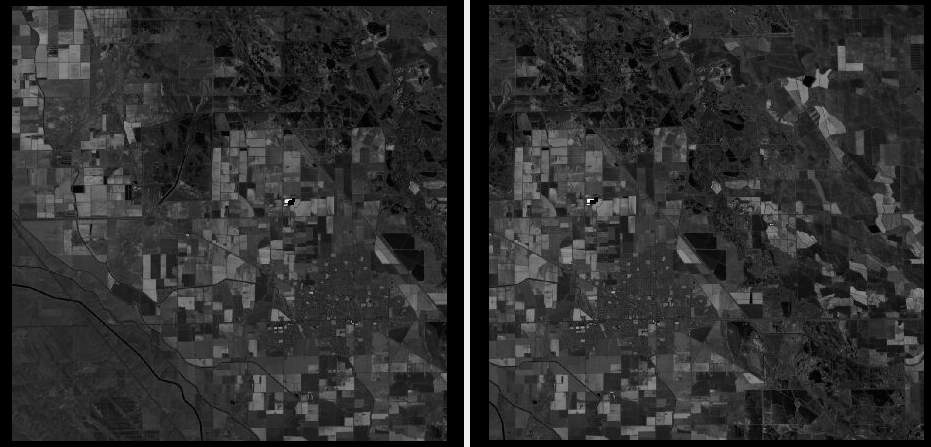
Fig. 10.4 A sample left and right image as produced by the rig (after mapprojection). The images have notable overlap. These show some fields and mountain foothills in California’s Central Valley.
10.4.3. Interest point matches
The rig_calibrator program expects the camera poses and the interest point
matches between images to be stored in an NVM file (a format commonly employed in
Structure-from-Motion applications). See Section 16.5.10.3.
Since there are 12 input images, and each must be matched against every other one, the Section 16.49 program is called to ensure parallelization:
parallel_bundle_adjust       \
  --ip-per-image 10000       \
  --output-cnet-type nvm     \
  sat_sim/*{left,right}.tif  \
  sat_sim/*{left,right}.tsai \
  --camera-weight 1.0        \
  --tri-weight 1.0           \
  --num-iterations 100       \
  -o ba/run
10.4.4. Rig calibration
The rig_calibrator program is then run:
rig_calibrator                                  \
  --rig-config sat_sim/run-nadir-rig_config.txt \
  --use-initial-rig-transforms                  \
  --fix-rig-translations                        \
  --nvm ba/run.nvm                              \
  --camera-poses-to-float "left right"          \
  --intrinsics-to-float                         \
  "left:focal_length right:focal_length"        \
  --camera-position-uncertainty 1.0             \
  --heights-from-dem aster_dem.tif              \
  --heights-from-dem-uncertainty 2.0            \
  --heights-from-dem-robust-threshold 0.1       \
  --tri-weight 1.0                              \
  --save-pinhole-cameras                        \
  --num-iterations 100                          \
  --out-dir rig
Since the input data is perfect, very few changes are expected. The produced
pinhole cameras (Section 20.1), saved in the output rig directory
(via the --save-pinhole-cameras option), should be very similar to the
initial inputs in the sat_sim directory.
The --heights-from-dem option demonstrates the new DEM constraint feature.
The implementation is as for bundle adjustment (Section 12.2.1.3).
Here we used --use-initial-rig-transforms because we start with a known rig,
rather than having to determine it from camera poses.
The option --fix-rig-translations is quite important for orbital rigs. The
distance between rig sensors is very small compared to the distance from the
satellite to the ground. Without this constraint the rig sensors could move
notably in the sensor plane without affecting the reprojection error.
Consider using here the option --camera-position-uncertainty. It is
suggested to be generous with the uncertainty value, as this constraint can
prevent convergence.
See Section 16.60.17 for the full list of options.